
Challenges of Designing Circuits for HDI Circuit Boards
Designing Circuits for HDI Circuit Boards
High-density circuit boards require more layers, thinner traces, and smaller vias than standard PCBs to accommodate the increased component and routing density. These higher densities create numerous challenges during fabrication, assembly, and testing. These challenges include the risk of impedance mismatches, signal loss, and component reliability issues. To minimize these challenges, it is important to use advanced design tools and follow the fabricator’s design for manufacturing (DFM) guidelines.
DFM is the process of designing a hdi circuit boards to meet the manufacturer’s manufacturing requirements. This involves creating an effective layout that ensures that the board’s physical and electrical characteristics are met. This requires a careful review of the board’s stack-up, via architecture, component placement, and BGA fanout. Choosing the right core substrate material is also important, as it determines the thickness of the conductive layers. The choice of finishing materials is another critical factor, as they affect the board’s cost. Common finish options include ENIG, immersion tin, and gold.
One of the biggest challenges in constructing hdi circuit boards is ensuring proper layer stacking and via orientation. This is because a misaligned stack-up can affect the performance of the board and lead to problems during soldering. The use of microvias and buried via technology helps to reduce the length of traces, which increases signal integrity. This can also decrease the capacitance and inductance of the circuit board.
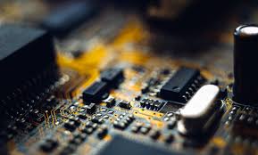
Challenges of Designing Circuits for HDI Circuit Boards
The stacked construction of HDI circuit boards also demands the use of blind and buried vias. These vias can be etched or drilled, and they must be aligned with the copper layers in the PCB. This requires a precise alignment process, which is done by using vision drill systems.
In addition, a faulty via structure can impact signal integrity. For example, if the vias are not properly centered or the hole diameter is too large, it can cause interference between adjacent signals. This can result in a loss of signal integrity and degrade the quality of the board’s performance.
To prevent this, it is necessary to perform EMI modeling during the layout phase to identify and extract parasitic capacitance and inductance. These models can be used to determine the best insertion point for each pin or pad, and help to minimize interference between signals.
In addition to the challenges mentioned above, the etching and imaging processes for HDI circuit boards are more complex than those for standard circuit boards. This is because of the finer lines and spacing in an HDI board, as well as the requirement for a semiconductor Class 100 clean room. This increase in complexity increases the production cost of the board. However, the increased reliability and speed of an HDI circuit board can make it worth the investment. For this reason, it is important to choose a good manufacturing partner for your project.