
How do you test a PCB prototype?
test a PCB prototype
Testing a PCB prototype is a critical step in the design and development process of any electronic device. The prototype is the first version of the printed circuit board (PCB) that represents the final product, and testing it ensures that the design functions as expected and meets all performance criteria. PCB testing helps identify issues early on, before mass production, saving time, money, and resources in the long run. There are several techniques and methods for testing a PCB prototype, each focusing on different aspects of the board’s functionality, performance, and reliability.
The first step in testing a PCB prototype is visual inspection. This is a straightforward yet essential process where engineers carefully examine the physical board for any visible defects, such as broken traces, misaligned components, soldering issues, or missing parts. Visual inspection can be done manually or with the help of automated optical inspection (AOI) machines, which use cameras and software to detect faults in the PCB. This initial inspection helps catch gross errors that could affect the functionality of the board.
Once the visual inspection is complete, engineers move on to electrical testing, which is one of the most important aspects of testing a pcb prototype. Electrical testing ensures that all connections are properly made and that the board functions as intended. A common method for electrical testing is the use of a continuity test, which checks for open circuits or short circuits by sending a small current through the traces and detecting whether the current flows as expected. Continuity testing helps identify issues such as broken or improperly connected traces, which can cause the board to malfunction.
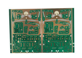
How do you test a PCB prototype?
Functional testing is another crucial aspect of testing a PCB prototype. This method involves powering the board and running it through a series of tasks to simulate its intended use. Functional tests verify that the PCB behaves as expected when it is in operation. For example, if the PCB is part of a microcontroller-based system, functional testing would involve checking whether the microcontroller processes inputs correctly, responds to outputs, and interacts properly with other components on the board. During this phase, engineers will also evaluate whether the PCB meets specific performance standards, such as signal integrity and voltage levels.
In addition to functional testing, stress testing is also performed on a PCB prototype to evaluate its durability and reliability under extreme conditions. Stress tests subject the PCB to higher-than-normal temperatures, voltages, or frequencies to determine how it behaves under stress. This helps identify any weaknesses in the design, such as thermal issues or components that could fail under heavy use. Stress testing is particularly important for products that will be used in harsh environments, such as automotive or aerospace applications.
Environmental testing is another key testing method, especially for PCB prototypes intended for use in specific environmental conditions. This may include subjecting the prototype to humidity, vibration, or extreme temperature fluctuations to ensure it can withstand the conditions it will face in real-world applications. For example, PCBs used in outdoor equipment or consumer electronics might undergo tests to ensure they can operate in high-humidity or extreme temperature environments without malfunctioning.
Once the electrical and functional performance is validated, engineers also conduct testing for electromagnetic compatibility (EMC). EMC testing ensures that the PCB prototype does not emit electromagnetic interference (EMI) that could disrupt nearby devices and, conversely, that it is not overly sensitive to external electromagnetic fields. This is especially critical for products that involve wireless communication or operate in regulated environments, such as medical devices or telecommunications equipment.
Finally, reliability testing is performed to assess the longevity and overall performance of the PCB prototype over time. This includes accelerated life testing, where the PCB is subjected to conditions that simulate extended use, helping to predict how the board will perform over its lifespan.